Chronus Heavy - The Design
Chronus Hobby - My 12lb Combat Robot
By: Julien Mott
Chronus is a design that I've worked towards for quite a while. I wanted to engineer something unique to other designs and my own—opening myself to that beyond my comfort zone while utilizing what is within. CNC milling, hub motors, and non-planar surfaces are a few sophisticated design constraints, but my duality simultaneously geared me to build the biggest and most powerful machine within my capabilities. Hundreds of amps to draw, over 3KJ of KE, 4lb (1/3 weight budget) allocated to the weapon assembly, and bronze anodization are a few unsophisticated design constraints


Chronus Hobby was designed with goals distinguished before the actual geometric deficient were collated and corrected, which consist of: The weapon being hub-motor driven, the robot to feature absolute use of BLDC technology, titanium to be used in the place of AR500 steel for armoring, and 3D printing technology to be implemented without the reduction of the capability of the overall whole.
The Hub Motor (9/17/2020)
To maximize the assurance of reliability, I've designed two hub motors: The first being a SHM (Simple Hub Motor) design, and the second being stylized after the BonX (More info on BonX) hub motor. The SHM, as the name implies, is an easier cognitive conception, but with a decrease in robustness, while the BonX style hub motor would be of greater reliability, but with more complicated fabrication and design processes. The latter requires the motor base to be removed from the stator, as well as the preload upon the hub to have less room for inaccuracy. The prior would be easier to implement into the design, as the motor base wouldn't require extrication, as well as the preload having a larger tolerance.

(Photo 2 - BonX style design config-1) (Photo 3 - SHM style design)
As is apparent, the prior photo shows a greater distance between the bearings while the latter has the bearings pressed to each other. In the final revision of SHM, the distance between them was increased to .28", but not great enough to disregard my fear of unreliability entirely. As of now (9/17/2020), I still need to identify the actions necessary to disjoin the stator base from the stator; the success of the BonX hub relies on the variable.
BonX Hub Motor config-2 (10/8/2020)
After over a month of experimentation with CAD, I've concluded that BonX hub motors are the way to go at this weight class. I've simplified the variables to only a single unknown: bearing load ratings. My options are to use 40x52x7MM bearings or 42x62x12MM bearings, with the latter weighing twice as much as the prior. Increasing the robustness of the system is desirable, but I've found that one overkill component results in another inaptitude. Because of this, I will have to build the robot with the exclusion of the hub motor and then decide once the robot's weight is beyond question, as weapon weight allocation will be with surety. Both config variants feature "static hubs" (Interfaces with bearing inner races) and "fly hubs" (Interface with bearing outer races). Then the .5625" titanium shaft (may be replaced with aluminum of a high-strength alloy) is used to redirect loads from the eight bolts constrain the static hubs to the weapon uprights, as shear is undesirable. Finally, the stator is retained to the shaft with a high-strength Loctite green glue. This allows for the greatest diameter shaft, but at the cost of it requiring retainment to prevent tangential motion, which would prevent weapon rotation of untreated. (Config-2 BonX)
 (Config-2 BonX)
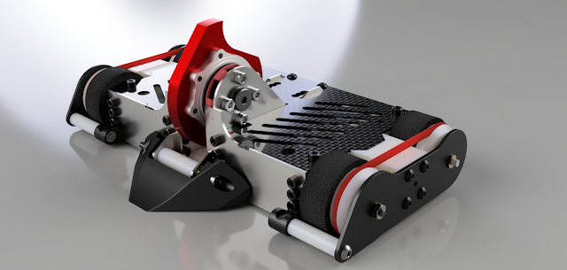
The Flywheel (9/17/2020)
As for the impactor flywheel itself, the weapon disc weighs in at 2.8lbs+the hub hardware, resulting in the spinning mass being ~3.2lbs, over 1/4th of the weight of the robot. With a 5.6" diameter, the KE (>3KJ) should be adequate for ceiling hits in the highest arenas in CA. I chose the geometry I did for the flywheel to maximize the inertia. As I was constrained to a .75" thick weapon and a 5.6" diameter, pocketing out the flywheel to increase the efficiency of energy storage/weight would be unrealistic (pockets would have contours less than the width of the material, resulting in geometrical inaccuracies, unbalancing the weapon and increasing cost of cutting and difficulty of cutting). The tooth protrudes only 3/8" from the opposing end, as the shape of the wedge would prevent the majority of horizontal spinner hits laterally to the axis of rotation of CH's flywheel. Because of this, the tooth's protrusion does not necessitate itself to have a larger rake to increase the likelihood of it receiving the better end of a weapon-on-weapon hit to a horizontal spinner. This maximizes stored energy, as the mass rotating at the furthest point from the central axis of rotation would have the highest aptitude to the increase in energy.
The Intake System (9/17/2020)

This orthographic view of CH better shows the size of the flywheel in proportion to the robot body. It also better shows the wedge (leading edge) path to the weapon. This intake system has side flaps at a 28-degree angle from the ground, which has proven itself an optimal angle for low resistance intake and deflection. Too shallow of an angle and the pressure upon the wheels in proportion to the pressure upon the third point of contact would become unbalanced, and the robot will not be able to drive forward. Too steep of a slope and the intake would become dysfunctional, as the deflectional properties would diminish and it would absorb the impact to a greater extent. It's a bell curve, and the highest point was discovered by Da Vinci 537 years ago. His tank was designed with an angle that optimizes deflection and its ability to not decrease but increase the downforce upon the wheels. This angle was 35-degrees. Of course, this angle was for an entirely different application. Da Vinci's tank was missing a certain property: Intake capabilities. His tank was designed to prevent enemy tanks from climbing up his wedge, as he didn't have a giant impactor flywheel on the top of his vehicle. By adjusting the wedge angle on my design, I can optimize the properties to allow for the best, or a large part of the good, of all worlds.

Though the weapon may seem anomalous with its large-diameter in relation to the rest of the robot, it allows for a fabulous position for the COM. If an opposing robot were to ride upon the wedge, the COM will move forward as well as lower. If the COM were to naturally be lower, the decreased elevation would make the pressure upon the third point of contact too great for a balanced system. Pressure upon this contact point would no longer be necessitated, as its job of intake is complete. Also, the distance along the x-axis is desirable as the pressure upon point three would be balanced in relation to the wheels.


Comments
Post a Comment